RZLblink/en: Unterschied zwischen den Versionen
KKeine Bearbeitungszusammenfassung |
(Projektkategorie „Elektronik“ setzen) |
||
| (3 dazwischenliegende Versionen von 3 Benutzern werden nicht angezeigt) | |||
| Zeile 1: | Zeile 1: | ||
{{LanguageBox |msg=Diese Seite gibt es auch auf Deutsch: [[RZLblink|hier]]}} | {{LanguageBox |msg=Diese Seite gibt es auch auf Deutsch: [[RZLblink|hier]]}} | ||
'''Caution! This page is not yet fully translated! Parts may be misleading. | |||
''' | |||
{{ProjektInfoBox | {{ProjektInfoBox | ||
|name = RZLblink | |name = RZLblink | ||
| Zeile 6: | Zeile 8: | ||
|image = blinkv21a.jpg | |image = blinkv21a.jpg | ||
|description = Let there be light using your blink(1) derivative. | |description = Let there be light using your blink(1) derivative. | ||
|author = [[user: | |category = Elektronik | ||
|author = [[user:muzy|muzy]] | |||
|username = | |username = | ||
|version = 2.1a | |version = 2.1a | ||
| Zeile 25: | Zeile 28: | ||
While soldering please do watch out to properly position the components according to the illustration below. All components are placed horizontally, the resitors R1 and R2 being the only exception since they ''have'' to be soldered in vertically. | While soldering please do watch out to properly position the components according to the illustration below. All components are placed horizontally, the resitors R1 and R2 being the only exception since they ''have'' to be soldered in vertically. | ||
[[Datei:RZLblinkBauteilPosition.png|thumb|410px| | [[Datei:RZLblinkBauteilPosition.png|thumb|410px|Before and after schematic for positioning the components]] | ||
# First you solder in the resistors R1 and R2 vertically. To do so you first moisten a pad with a bi of solder. Then you pick up the component with a pair of pliers (hold them in your non-writing hand) and re-heat the solder. Now you carefully push the component into the liquid solder until it is in the correct position. Then you take the soldering iron away from the solder and wait for the solder to solidify while still holding it in position with your pliers. Once it has solidified, you can release the component. | |||
# Repeat these steps for the capacitors C1 and C2 as well as the resistor R3 and fuse F1. | |||
# Now solder in the resistors R4, R5 and R6 in similar fashion. Always be mindful where you place which one since mistaking one for another will cause your RZLblink to not work properly and might also shorten the components lifetime. | |||
# Continue with diode D1. | |||
# Weiter geht es mit der Diode D1. Hier verzinnst du am besten das einzelne Lötpad und lötest, analog zu den Widerständen, das einzelne Beinchen fest. Dabei kannst du das Bauteil direkt richtig ausrichten. Genauso wird auch der Microcontroller aufgelötet. Achte auf die Orientierung; ein kleiner Punkt markiert Pin 1. Hier empfiehlt es sich zunächst diagonal liegende Beinchen anzulöten und danach den Rest | # Weiter geht es mit der Diode D1. Hier verzinnst du am besten das einzelne Lötpad und lötest, analog zu den Widerständen, das einzelne Beinchen fest. Dabei kannst du das Bauteil direkt richtig ausrichten. Genauso wird auch der Microcontroller aufgelötet. Achte auf die Orientierung; ein kleiner Punkt markiert Pin 1. Hier empfiehlt es sich zunächst diagonal liegende Beinchen anzulöten und danach den Rest | ||
# Zuletzt folgen die LED und der USB-Stecker. Die LED darf nicht zu warm werden, daher diese bitte vorsichtiger löten. Etwas Flussmittel hilft hier, das Lötzinn unter die LED zu bekommen. | # Zuletzt folgen die LED und der USB-Stecker. Die LED darf nicht zu warm werden, daher diese bitte vorsichtiger löten. Etwas Flussmittel hilft hier, das Lötzinn unter die LED zu bekommen. | ||
| Zeile 40: | Zeile 47: | ||
== Software == | == Software == | ||
The RZLblink is already flashed with the fine Software from ThingM ([https://github.com/todbot/blink1/ Github Source]) and posesses a unique serial-id. The client-software for your PC can also be found following that [https://github.com/todbot/blink1/ link]. | |||
For initial tests using linux the blink1-tool is recommended. Maybe a UDEV-Rule has to be configured appropriately or you could run the programm as root-user. | |||
== Case == | |||
operative from the [https://wiki.chaosdorf.de/Chaosdorf Chaosdorf] has designed a Case for printing with a 3D-printer. It can be found here: | |||
* [https://tinkercad.com/things/6Ee6jyoB2tE-rzlblink-deckel RZLblink Lid] | |||
* [https://tinkercad.com/things/hDbEDJYCFHf-rzlblink-unterseite RZLblink Bottom shell] | |||
echox from [https://raumzeitlabor.de/ Raumzeitlabor] has designed a closed version: [http://www.thingiverse.com/thing:129772 Pictures and OpenSCAD-files] | |||
== F.A.Q. == | == F.A.Q. == | ||
''' | '''RZLblink only lights up briefly when i plug it into the USB-Port''' | ||
:'' | :''RZLblink notices when it is plugged into an USB-port of a PC and then waits for commands. If it only gets 5 Volt and no data-connectivity, it will only blink an initial code of "red green blue". | ||
'' | '' | ||
''' | '''I cannot see the RZLblink at the USB port but it is fading the combination "red green blue".''' | ||
:'' | :''You probably soldered in R1 and R2 horizontally instead of vertically. Please refer to the schematic plan to see if they are inserted in the correct orientation. | ||
'' | '' | ||
''' | '''My RZLblink just doesn't work''' | ||
:'' | :''Re-solder any soldering spots that don't look flawless and test individual connections with a multimeter. If all is looking fit, solder wires to the six Programming-connectors and try flashing the firmware again. We're happy to be of assistance for you. | ||
'' | '' | ||
| Zeile 69: | Zeile 80: | ||
!Lizenz | !Lizenz | ||
|- | |- | ||
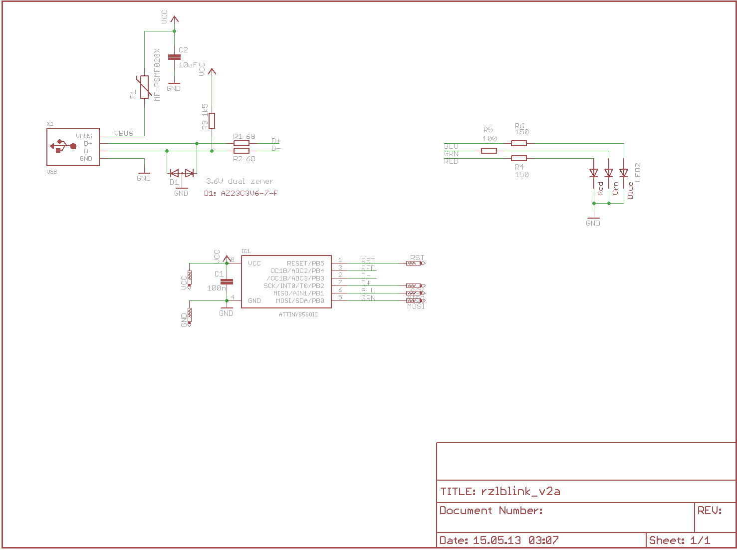
| | |circuit-diagram | ||
|[[Medium:SchaltplanRzlBlink.png|.png]] | |[[Medium:SchaltplanRzlBlink.png|.png]] | ||
|CC-BY-ND | |CC-BY-ND | ||
|- | |- | ||
| | |list of parts | ||
|[[Medium:Parts.txt?|.txt]] | |[[Medium:Parts.txt?|.txt]] | ||
|CC0 | |CC0 | ||
| Zeile 79: | Zeile 90: | ||
|Sourcecode (Github) | |Sourcecode (Github) | ||
|[https://github.com/todbot/blink1] | |[https://github.com/todbot/blink1] | ||
|CC-BY | |CC-BY-SA | ||
|- | |- | ||
|} | |} | ||
== Firmware Mods == | == Firmware Mods == | ||
| Zeile 109: | Zeile 119: | ||
[[Kategorie:Raum-Kommerz-Labor]] | [[Kategorie:Raum-Kommerz-Labor]] | ||
[[Kategorie:Shop]] | [[Kategorie:Shop]] | ||
[[ | [[Category:Wiki Cleanup/ToDo ]] | ||
Aktuelle Version vom 12. Dezember 2019, 19:23 Uhr
| Diese Seite gibt es auch auf Deutsch: hier |
Caution! This page is not yet fully translated! Parts may be misleading.
| RZLblink Release status: stable [box doku] | |
|---|---|

| |
| Beschreibung | Let there be light using your blink(1) derivative. |
| Kategorie | Elektronik |
| Autor(en) | muzy |
| Letzte Version | 2.1a |
| Mindestpreis/Bausatz | (Price) 8€ per kit |
RZLblink is your Do-It-Yourself USB RGB LED and is based on the blink(1) found on ThingM[1]. Whether as a flashy Lightsource or as a display for status-notification: RZLblink is a Highlight!
Assembly
Assembly of the RZLblink is rather easy! Follow the following steps and don't fear the Soldering iron. The only heat-sensitive components are the Microcontroller (packaged in antistatic bags) and the LED.
While soldering please do watch out to properly position the components according to the illustration below. All components are placed horizontally, the resitors R1 and R2 being the only exception since they have to be soldered in vertically.

- First you solder in the resistors R1 and R2 vertically. To do so you first moisten a pad with a bi of solder. Then you pick up the component with a pair of pliers (hold them in your non-writing hand) and re-heat the solder. Now you carefully push the component into the liquid solder until it is in the correct position. Then you take the soldering iron away from the solder and wait for the solder to solidify while still holding it in position with your pliers. Once it has solidified, you can release the component.
- Repeat these steps for the capacitors C1 and C2 as well as the resistor R3 and fuse F1.
- Now solder in the resistors R4, R5 and R6 in similar fashion. Always be mindful where you place which one since mistaking one for another will cause your RZLblink to not work properly and might also shorten the components lifetime.
- Continue with diode D1.
- Weiter geht es mit der Diode D1. Hier verzinnst du am besten das einzelne Lötpad und lötest, analog zu den Widerständen, das einzelne Beinchen fest. Dabei kannst du das Bauteil direkt richtig ausrichten. Genauso wird auch der Microcontroller aufgelötet. Achte auf die Orientierung; ein kleiner Punkt markiert Pin 1. Hier empfiehlt es sich zunächst diagonal liegende Beinchen anzulöten und danach den Rest
- Zuletzt folgen die LED und der USB-Stecker. Die LED darf nicht zu warm werden, daher diese bitte vorsichtiger löten. Etwas Flussmittel hilft hier, das Lötzinn unter die LED zu bekommen.
- Ist auch der USB-Stecker angelötet, empfiehlt es sich hier mit einer Flachzange die seitlichen Beinchen zur Platine zu biegen um den Stecker mechanisch weiter zu fixieren.
Software
The RZLblink is already flashed with the fine Software from ThingM (Github Source) and posesses a unique serial-id. The client-software for your PC can also be found following that link.
For initial tests using linux the blink1-tool is recommended. Maybe a UDEV-Rule has to be configured appropriately or you could run the programm as root-user.
Case
operative from the Chaosdorf has designed a Case for printing with a 3D-printer. It can be found here:
echox from Raumzeitlabor has designed a closed version: Pictures and OpenSCAD-files
F.A.Q.
RZLblink only lights up briefly when i plug it into the USB-Port
- RZLblink notices when it is plugged into an USB-port of a PC and then waits for commands. If it only gets 5 Volt and no data-connectivity, it will only blink an initial code of "red green blue".
I cannot see the RZLblink at the USB port but it is fading the combination "red green blue".
- You probably soldered in R1 and R2 horizontally instead of vertically. Please refer to the schematic plan to see if they are inserted in the correct orientation.
My RZLblink just doesn't work
- Re-solder any soldering spots that don't look flawless and test individual connections with a multimeter. If all is looking fit, solder wires to the six Programming-connectors and try flashing the firmware again. We're happy to be of assistance for you.
Download
| Datei | Format | Lizenz |
|---|---|---|
| circuit-diagram | .png | CC-BY-ND |
| list of parts | .txt | CC0 |
| Sourcecode (Github) | [2] | CC-BY-SA |
Firmware Mods
- Man kann bis zu 12 Pattern (Zeit und Farbwert) im EEPROM von RZL-Blink ablegen. Diese Pattern können dann mit dem Befehl "p" abgespielt werden. Optional kann die Startposition als Parameter mitgegeben werden. Dann werden die vorher programmierten Pattern ab dieser Position abgespielt. Es sind 12 Pattern möglich. Dummerweise startet die Firmware nach dem 12. Pattern wieder bei 0 und nicht bei der vorher übergebenen Position. Bug oder Feature? Ich habe keine Ahnung, habe aber die zwei fehlenden Zeilen hier eingefügt.
- Firmware neu Flashen über SPI ... warum? Schließlich hat das RZL-Blink den doppelten Speicher von blink(1) (ATtiny85 statt ATtiny45) und einen USB-Anschluss. Da ist noch genug Platz für einen 2KB USB-Bootloader. Ich packe hier mal ein fertiges hex file hin, dann müsst ihr nicht selbst konfigurieren und den alten avr-gcc4.3.3 rauskramen, um es zu kompilieren. (Link kommt noch)
Bilder
 |
 |
 |
Beispiel Applikationen
Gleitzeitampel
Die Gleitzeitampel steckt im Bürorechner. Wird dieser morgens eingeschaltet, prüft das Programm, ob er heute zum ersten Mal eingeschaltet wurde. Ist dies der Fall, wird eine Timestamp in die Settings.ini geschrieben. Im Anschluss prüft das Programm alle 5 sec, ob die Sollzeit für diesen Tag erreicht ist und wechselt, falls ja, die Farbe auf Gelb. Man kann nun gehen, ohne Verlust zu machen. Außerdem kann man festlegen, wie viel Zeit man pro Tag gerne aufbauen möchte. Ist die Sollzeit + die Aufbauzeit erreicht, wechselt die Ampel auf grün.
Die erste schmutzige aber getestete Version liegt auf Github. Feel free to improve.
Binaries gibts hier.
--ThinkJD (Diskussion) 10:13, 15. Aug. 2013 (CEST)