Hacklace/en: Unterschied zwischen den Versionen
Muzy (Diskussion | Beiträge) |
Muzy (Diskussion | Beiträge) Keine Bearbeitungszusammenfassung |
||
| (22 dazwischenliegende Versionen von 7 Benutzern werden nicht angezeigt) | |||
| Zeile 1: | Zeile 1: | ||
{{AchtungKasten1 |title= Project no longer maintained |msg= | |||
The project "Hacklace" is no longer maintained. This site is for reference only.}} | |||
{{LanguageBox |msg=This page was translated from the German version. Click [[Hacklace|here]] to visit the original page.}} | {{LanguageBox |msg=This page was translated from the German version. Click [[Hacklace|here]] to visit the original page.}} | ||
{{ProjektInfoBox | {{ProjektInfoBox | ||
| Zeile 30: | Zeile 30: | ||
* Coin cell included | * Coin cell included | ||
* Symmetric component layout | * Symmetric component layout | ||
* | * Adjustable pin mapping to support dot-matrix display types | ||
* Supports ASCII including german umlauts and additional symbols | * Supports ASCII including german umlauts and additional symbols | ||
* Propotional font and predefined animations included | * Propotional font and predefined animations included | ||
| Zeile 43: | Zeile 43: | ||
Using the hacklace is very easy, because there is just one button which triggers the actions. | Using the hacklace is very easy, because there is just one button which triggers the actions. | ||
By pressing this button short time, the hacklace switches to the next text/animation. By pressing the button | By pressing this button for a short period of time, the hacklace switches to the next text/animation. By pressing the button longer, the hacklace goes into a deep sleep mode which consumes nearly no power. By pressing the button again, the hacklace resumes from deep sleep. | ||
==Prerequisites== | ==Prerequisites== | ||
Building the hacklace will help you learn to solder. If you already have soldering experience and | Building the hacklace will help you learn how to solder. If you already have soldering experience and knowledge how to flash AVR mircocontrollers, it should be easy for you to build one. If you are not used to the tasks of soldering and flashing a microcontroller, we recommend to ask some RaumZeitLabor member to help you. This way you will gain the needed expertise! | ||
==Tools needed== | ==Tools needed== | ||
| Zeile 54: | Zeile 54: | ||
* ISP programmer for Atmel AVR-microcontroller | * ISP programmer for Atmel AVR-microcontroller | ||
* A computer | * A computer | ||
* Optional: equipment for etching circuit boards (when you do not want to use | * Optional: equipment for etching circuit boards (when you do not want to use one of our pre-produced circuit boards) | ||
Everything you | Everything you need is readily available at the RaumZeitLabor. Ask a friendly hackerspace member to introduce you to the equipment. | ||
==Hardware== | ==Hardware== | ||
=== | ===Circuit Board=== | ||
[[Datei:Hacklace_Platine.jpg|thumb|right|220px| | [[Datei:Hacklace_Platine.jpg|thumb|right|220px|Circuit board, etched manually and painted red]] | ||
The circuit board was designed to be easily etched. If you want to etch the circuit by yourself you will find the file [[Hacklace/en#Download|here]]. | |||
After you etched the pcb you just need two drilling diameters. Use a 1.2mm (0.047") diameter for the LED-matrix pins and the tactile-switch pins. Apart from those drill holes, the remaining drill holes should have a diameter of 0.9mm (0.035"). The pads on the upper left and upper right side are not part of the circuit and can be drilled to the diameter of the cable which acts as the holder for the necklace. | |||
In case you do not have the equipment for etching circuit boards, you can buy a professionally manufactured circuit board [[Hacklace#Bezugsquellen|here]]. | |||
===Assembly=== | |||
=== | ====Hint on the display==== | ||
Due to shortages in hardware supply, there are 3 different display types. Depending on the type, the display has to be inserted differently. This is also a configuration parameter in the firmware. | |||
# HDSP-5403 hp 008 L3 - The black dot on the side of the display has to be arranged diagonally to PIN 1 (rectangular pad). Seen from top, that's the bottom right edge. Note: Since 01/2013 this display type is obsolete and will no longer be delivered with our kits. | |||
# TC07 / TA07 - Pin 1 of the display (rectangular pad) is in the same row as pin 1 of the micro-controller (square pad). Depending on the display type (TA or TC) the corresponding firmware has to be flashed. | |||
# LM57 - Same as TC07 display. Pin 1 of the display has been manually marked with a felt tip marker. | |||
====Instructions==== | |||
Important: The top of the PCB is the side without traces and text! That's the side which is visible while waring. The traces and silkscreen are located on the back side. The back side is where you'll be soldering the components. | |||
[[Datei:Hacklace_Zusammenbau01.jpg|thumb|right|220px|SMD Resistors]] | |||
[[Datei:Hacklace_Zusammenbau01.jpg|thumb|right|220px|SMD | [[Datei:Hacklace_Zusammenbau02.jpg|thumb|right|220px|Resistors and Capacitor]] | ||
[[Datei:Hacklace_Zusammenbau02.jpg|thumb|right|220px| | [[Datei:Hacklace_Zusammenbau03.jpg|thumb|right|220px|Aligning the IC Pins]] | ||
[[Datei:Hacklace_Zusammenbau03.jpg|thumb|right|220px| | |||
The assembling is done as follows: | |||
# | # Firstly, the two SMD resistors ('''R2''', '''R3''') are soldered to the conductor path side. Due to the large 1206 type, this is comparatively easy. At first, cover one pad with solder, then hold the resistor to the pad with a pair of tweezers. As soon as the part fits correctly, do the same with the other connector. | ||
# | # Bend the pins of the through-hole resistor '''R1''' in the correct width. You can use a bending tool. Insert the resistor into the holes. Fixate the resistor with a piece of tape. Turn the PCB around and solder the pins. Cut the remainder of the pins with a sidecutter. | ||
# | # Repeat with the capacitor ('''C1'''). | ||
# | # If you don't like the white case of the display, paint it black using a permanent marker. | ||
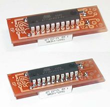
# ICs usually don't come bent to the 2.54mm grid common in through-hole technology. You need to bend them to that grid first by either using a bending tool or by hand (see photo). Additionally, it is recommended to pre-tin the pins of the display a bit with solder. | |||
# | # Now it's time for a tricky bit: The dot-matrix display and the IC need to be soldered in '''at the same time'''. Insert the display from the top and apply a bit of tape to hold it in place, but don't solder it in yet! The display is supposed to fit into the pads with the larger holes. You can recognize the first pad for the IC by it's squre shape (Pin 1). The first pin of the display is labeled with a small "1" or a dot. The pins of the display needs to be cut so that they'll stick out of the PCB by about 1mm. Insert the IC from the opposite side. This requires a bit of trial-and-error until all the pins fit. | ||
# | # Solder the pins of the display and the IC. Apply a bit of solder flux to achieve better bonding. As we're soldering directly on the pins themselves you should wait a while after soldering one pin so that the parts don't overheat while soldering (this could break the uC) | ||
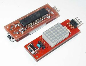
# | # Insert the button and the pin header on the top and solder it from the bottom. | ||
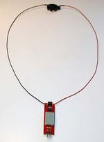
# | # Solder the two wires (red = positive, black = negative) to their corresponding pads. Then cut the wires to the desired length. To reduce mechanical stress you should guide both cables through their cable holes in the top of the PCB. | ||
# | # Last Step! You need to solder the wires to the battery holder. You need to make sure that the polarity is correct, as the hacklace doesn't provide polarity protection. You may want to bend the pins of the battery holder so that you don't prick your neck. | ||
{| | {| | ||
| [[Datei:Hacklace_Zusammenbau05.jpg|thumb|right|220px| | | [[Datei:Hacklace_Zusammenbau05.jpg|thumb|right|220px|Soldering of the IC and display (before, after)]] | ||
| [[Datei:Hacklace_Zusammenbau07.jpg|thumb|right|300px| | | [[Datei:Hacklace_Zusammenbau07.jpg|thumb|right|300px|Pin header and button]] | ||
| [[Datei:Hacklace_Zusammenbau08.jpg|thumb|right|150px| | | [[Datei:Hacklace_Zusammenbau08.jpg|thumb|right|150px|Completed hacklace with wires and battery holder]] | ||
|} | |} | ||
=== | ===Flash the firmware=== | ||
To flash the firmware you'll need an AVR programmer (the [[Usbasp|USBAsp]] is such a programmer). Connect your programmer to the ISP interface on the hacklace. | |||
The fuses for the attiny4313 need to be adjusted so that the controller runs at 4 MHz from it's internal RC Oscillator. The fuses are: Low: 0xE2 High: 0xDF Extended: 0xFF | |||
Set the fuse bits using avrdude: | |||
avrdude -v -c <PROGRAMMER> -p t4313 -U lfuse:w:0xe2:m -U hfuse:w:0xdf:m -U efuse:w:0xff:m | avrdude -v -c <PROGRAMMER> -p t4313 -U lfuse:w:0xe2:m -U hfuse:w:0xdf:m -U efuse:w:0xff:m | ||
<PROGRAMMER> | Replace <PROGRAMMER> with your used programmer, e.g. '''usbasp''' | ||
Now program the firmware and the eeprom configuration data. | |||
Program flash and eeprom using avrdude: | |||
avrdude -c usbasp -p t4313 -u -U eeprom:w:Hacklace_Rev_B.eep | avrdude -c usbasp -p t4313 -u -U eeprom:w:Hacklace_Rev_B.eep | ||
avrdude -c usbasp -p t4313 -u -U flash:w:Hacklace_Kingbright_TA.hex | avrdude -c usbasp -p t4313 -u -U flash:w:Hacklace_Kingbright_TA.hex | ||
| Zeile 120: | Zeile 120: | ||
==Software== | ==Software== | ||
=== | === Compiling the firmware === | ||
The firmware for the attiny4313 was developed using AVR-Studio 6.0 from Atmel (AVR Toolchain Version: 3.4.0.663 - GCC 4.6.2). The contained file "iotn4313.h" has an error. A corrected version of that file is available in the GIT-Repository. Place the corrected file under Windows to "C:\Programme\Atmel\Atmel Studio 6.0\extensions\Atmel\AVRGCC\3.4.0.65\AVRToolchain\avr\include\avr". | |||
"C:\Programme\Atmel\Atmel Studio 6.0\extensions\Atmel\AVRGCC\3.4.0.65\AVRToolchain\avr\include\avr" | |||
If you're compiling manually using the avr-gcc toolchain, you should pass the compiler flags "-Os" (to optimize code size only) as well as "-DF_CPU=4000000" (to set the target CPU frequency to 4MHz). | |||
=== | ===Display Memory=== | ||
[[Datei:Hacklace_Display_Schema.png|thumb|right|300px]] | [[Datei:Hacklace_Display_Schema.png|thumb|right|300px]] | ||
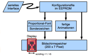
The hacklace uses 200 bytes of display memory. Each byte represents one column of the display. The hacklace uses a proportional font by default. As such, most characters have a width of 4 columns plus one empty column for spacing. Animations are composited of single frames, where each frame requires 5 bytes. The maximum animation size is 40 frames, so also text messages are limited to about 40 characters. | |||
===Configuration=== | |||
You can store custom texts and animations via a serial interface. You'll need a 3.3 or 5V serial cable. Connect it to CON2 (Pin 1: GND, Pin 2: TxD, Pin 3: RxD). Serial configuration: 2400 Baud, 8 data bits, no parity, 1 stop bit [8N1]). | |||
The text file configures your own texts or animations. You can edit it with any text editor. Make sure you're using an 8 bit ASCII encoding; UTF-8 is not supported. The maximum length of the configuration file is 256 bytes due to the microcontroller's eeprom memory. | |||
You need to send a specific init sequence to avoid programming by accident. Send the following sequence to your hacklace: | |||
Escape-Character (ASCII Code 27, resets the hacklace) | |||
Capital H, Capital L | |||
Now you can transfer the configuraion file. It is recommended to reset the hacklace again after you've transferred the file. This enables write protection. | |||
===Configuration file format=== | |||
One messge is either one text or one animation. You can cycle though the messages by pushing the button. Each line of the configuration file contains exactly one message. A message always begins with a mode byte, followed by text or the data of the animation. A mode byte of 0 designates the end of the message list. | |||
The mode byte is defined as follows: | |||
* Bit 7: forward (0) or backward (1) scrolling | |||
* Bit 6..4: Duration of the pause after the end of the message | |||
* Bit 3: Text (0) or Animation (1) | |||
* Bit 2..0: Scroll speed | |||
Don't set all bits to zero, as this designates the end of the message list. | |||
You can enter texts as plain text. You can use any printable 7-bit ASCII characters as well as the german umlauts ([[Medium:Hacklace_Font_5x7_extended.bmp|Hacklace charset]]). | |||
The hacklace firmware supports escape chars to make entering special chars, animations and byte values easier: | |||
* Prefix with a '^' to increase the char value by 63. Example: '^A' represents the first special character (129), '^B' the second (130). | |||
* Prefix with a '~' chooses an animation stored in flash. Example: '~A' chooses the first animation, '~B' the second one. | |||
* Prefix with a '$' to enter hexidecimal values. Example: '$10' or '$A1'. You need to enter exactly two values. Only capital letters are allowed. Use space or colon to exit the hex mode. | |||
* Use '^^', '~~' or '$$' to represent the literal value. | |||
You can program own animations by entering the direct mode using '$FF'. Any bytes now entered will be directly stored into flash. Each byte represents a display column, where bit 0 is the first line and bit 6 the last line. bit 7 is not used and should be set to 0. Exit the direct mode by sending a character of value 255. | |||
Configuration example: | |||
<code> | <code> | ||
$45, | $45,Sample text | ||
$40, | $40, Very slow scrolling | ||
$47, | $47, now very fast | ||
$74, | $74,medium speed with pause | ||
$84,. | $84,.bidirectional. | ||
$44, | $44,Umlauts äÄöÖüÜß | ||
$24, | $24,A heart ^R | ||
$3B,~F | $3B,~F | ||
$0C,$FF $55 $2A $55 $2A $55 $2A $55 $2A $55 $2A $FF, | $0C,$FF $55 $2A $55 $2A $55 $2A $55 $2A $55 $2A $FF, | ||
| Zeile 173: | Zeile 177: | ||
</code> | </code> | ||
=== | ===Creating animations=== | ||
'''You can use the hacklace animator tool to create own animations: [https://github.com/Hacklace/Animator/wiki/Download https://github.com/Hacklace/Animator/wiki/Download]''' | |||
You need to create your own header file if you wish to replace the animations. That header file contains your animation data as byte array. Include a #include command into "animations.h" which will include your own header file. You'll also need to append your animation to the list of animations (animation[]). The position inside that list defines which character is assigned to it. For example, '~A' is the first animation inside that list (see [[Hacklace/en#Configuration file format|Configuration File]]). | |||
You can use the [[Medium:Hacklace_Animationtemplate.bmp|Hacklace Template]] to make it easier to create animations. It is a greyscale image with 40 frames with 5x8 pixels each. You can simply draw your frames using a bitmap paint program. The last line (8) is not used. To turn on a pixel, draw using color code 0, to turn it off draw using color code 255. Greyscale values are ignored. Crop the image to the number of used frames. Use the script "[[Medium:make_data.m|make_data.m]]" to convert your image to a C header file. Enter the file name without extension, e.g. make_data('my_animation'). You'll need FreeMat, a free Matlab clone. | |||
==Download== | ==Download== | ||
{| class="wikitable" valign = "top" | {| class="wikitable" valign = "top" | ||
! | !File | ||
!Format | !Format | ||
! | !License | ||
|- | |- | ||
| | |Schematic | ||
|[[Medium:Hacklace_Schematic_Rev_B.pdf|.pdf]] | |[[Medium:Hacklace_Schematic_Rev_B.pdf|.pdf]] | ||
|CC-BY-ND | |CC-BY-ND | ||
|- | |- | ||
| | |Bill of Materials | ||
|[[Medium:Hacklace_Bauteileliste.pdf|.pdf]] | |[[Medium:Hacklace_Bauteileliste.pdf|.pdf]] | ||
|CC0 | |CC0 | ||
|- | |- | ||
| | |PCB etching template | ||
|[[Medium:Hacklace_PCB_20x_Rev_B.pdf|.pdf]] | |[[Medium:Hacklace_PCB_20x_Rev_B.pdf|.pdf]] | ||
|CC-BY-ND | |CC-BY-ND | ||
|- | |- | ||
| | |Assembly Plan (front and back) | ||
|[[Medium:Hacklace_Assembly_Front_Side_Rev_B.pdf|.pdf]], [[Medium:Hacklace_Assembly_Copper_Side_Rev_B.pdf|.pdf]] | |[[Medium:Hacklace_Assembly_Front_Side_Rev_B.pdf|.pdf]], [[Medium:Hacklace_Assembly_Copper_Side_Rev_B.pdf|.pdf]] | ||
|CC-BY-ND | |CC-BY-ND | ||
|- | |- | ||
| | |Firmware (Display Kingbright TA07-11) | ||
|[[Medium:Hacklace_Kingbright_TA.hex|.hex]] | |[[Medium:Hacklace_Kingbright_TA.hex|.hex]] | ||
|CC-BY-NC-ND | |CC-BY-NC-ND | ||
|- | |- | ||
| | |Firmware (Display Kingbright TC07-11) | ||
|[[Medium:Hacklace_Kingbright_TC.hex|.hex]] | |[[Medium:Hacklace_Kingbright_TC.hex|.hex]] | ||
|CC-BY-NC-ND | |CC-BY-NC-ND | ||
|- | |- | ||
| | |Firmware (Display HDSP-5403) | ||
|[[Medium:Hacklace_HDSP5403.hex|.hex]] | |[[Medium:Hacklace_HDSP5403.hex|.hex]] | ||
|CC-BY-NC-ND | |CC-BY-NC-ND | ||
|- | |- | ||
| | |EEPROM hex file | ||
|[[Medium:Hacklace_Rev_B.eep|.eep]] | |[[Medium:Hacklace_Rev_B.eep|.eep]] | ||
|CC-BY-NC-ND | |CC-BY-NC-ND | ||
|- | |- | ||
| | |Source code (Github) | ||
|[https://github.com/fabster/Hacklace] | |[https://github.com/fabster/Hacklace] | ||
|CC-BY-NC-SA | |CC-BY-NC-SA | ||
|} | |} | ||
All files are published under the respective Creative-Commons license. | |||
== | ==Pictures== | ||
{| | {| | ||
| [[Datei:Hacklace_Halskette.jpg|thumb|left|300px| | | [[Datei:Hacklace_Halskette.jpg|thumb|left|300px|Hacklace worn as necklace]] | ||
| [[Datei:Hacklace_Skull_red.jpg|thumb|left|250px| | | [[Datei:Hacklace_Skull_red.jpg|thumb|left|250px|Hacklace worn as belt clip]] | ||
|} | |} | ||
The belt clip was made by attaching the battery holder to a PCB and connected using soldering lugs. | |||
You can see the hacklace on a video on YouTube [http://www.youtube.com/watch?v=6ASvxaGiPwA]. | |||
==Ordering Information== | |||
In Germany, you can order all needed parts from Reichelt or CSD-Electronics. A list of parts can be found [[Medium:Hacklace_Bauteileliste.pdf|here]]. | |||
| | |||
=== Kit === | |||
You can purchase a kit for 10€ at RaumZeitLabor - please contact [[Benutzer:muzy|muzy]]. | |||
{| | {| | ||
| [[Datei:Hacklace_Einzelteile.jpg|thumb|right|260px| | | [[Datei:Hacklace_Einzelteile.jpg|thumb|right|260px|Parts]] | ||
| [[Datei:Hacklace_Platine_schwarz.jpg|thumb|right|120px| | | [[Datei:Hacklace_Platine_schwarz.jpg|thumb|right|120px|PCB]] | ||
| [[Datei:Hacklace_schwarz.jpg|thumb|right|240px| | | [[Datei:Hacklace_schwarz.jpg|thumb|right|240px|Completed Hacklace]] | ||
|- | |- | ||
|} | |} | ||
==Credits== | ==Credits== | ||
Hacklace | Hacklace was inspired by the "TinyMatrix" project from TigerUp [https://sites.google.com/site/tinymatrix/]. | ||
[[Kategorie:Projekt]] | [[Kategorie:Projekt]] | ||
[[Category:Raum-Kommerz-Labor]] | |||
[[Category:Shop]] | |||
Version vom 25. Februar 2014, 17:19 Uhr
| Achtung: Project no longer maintained | ||
|---|---|---|
| The project "Hacklace" is no longer maintained. This site is for reference only. |
| This page was translated from the German version. Click here to visit the original page. |
| Hacklace Release status: stable [box doku] | |
|---|---|
| |
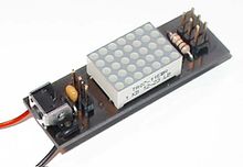
| Beschreibung | A necklace with a 5x7 dotmatrix display |
| Autor(en) | fabster, muzy |
| Letzte Version | Revision B |
| Lizenz | Creative Commons |
| Download | Download |
Hacklace - A Necklace for Hackers
- You're searching for an accessory suitable for nerds, geeks and hackers? Try a hacklace!
- You're searching for an individual gift? Try a hacklace!
- You want to be the highlight on any party? A hacklace is your gadget with which you can gain attention!
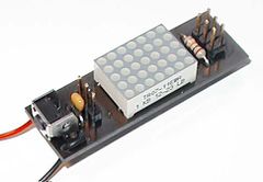
A hacklace is 5x7 dotmatrix display which is attached to a necklace. You can create your own animations and messages which one can display on the dotmatrix display. You are only limited by your own imagination.
Features
- Only 48mm x 15mm (1.89" x 0.59") in size.
- Coin cell included
- Symmetric component layout
- Adjustable pin mapping to support dot-matrix display types
- Supports ASCII including german umlauts and additional symbols
- Propotional font and predefined animations included
- Serial port (3,3 or 5V) to upload your own messages and animations which are then stored in the EEPROM.
- Animations and messages can be created easily using a text-editor of your choice.
- Ready to use. Your hacklace microcontroller comes with the latest firmware.
- Speed, delay and modus can be set individually.
- ISP-connector for flashing custom firmware.
Usage
Using the hacklace is very easy, because there is just one button which triggers the actions.
By pressing this button for a short period of time, the hacklace switches to the next text/animation. By pressing the button longer, the hacklace goes into a deep sleep mode which consumes nearly no power. By pressing the button again, the hacklace resumes from deep sleep.
Prerequisites
Building the hacklace will help you learn how to solder. If you already have soldering experience and knowledge how to flash AVR mircocontrollers, it should be easy for you to build one. If you are not used to the tasks of soldering and flashing a microcontroller, we recommend to ask some RaumZeitLabor member to help you. This way you will gain the needed expertise!
Tools needed
To build a hacklace you'll need the following tools:
- Soldering equipment (Soldering iron, solder, tweezers, ...)
- ISP programmer for Atmel AVR-microcontroller
- A computer
- Optional: equipment for etching circuit boards (when you do not want to use one of our pre-produced circuit boards)
Everything you need is readily available at the RaumZeitLabor. Ask a friendly hackerspace member to introduce you to the equipment.
Hardware
Circuit Board
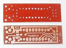
The circuit board was designed to be easily etched. If you want to etch the circuit by yourself you will find the file here.
After you etched the pcb you just need two drilling diameters. Use a 1.2mm (0.047") diameter for the LED-matrix pins and the tactile-switch pins. Apart from those drill holes, the remaining drill holes should have a diameter of 0.9mm (0.035"). The pads on the upper left and upper right side are not part of the circuit and can be drilled to the diameter of the cable which acts as the holder for the necklace.
In case you do not have the equipment for etching circuit boards, you can buy a professionally manufactured circuit board here.
Assembly
Hint on the display
Due to shortages in hardware supply, there are 3 different display types. Depending on the type, the display has to be inserted differently. This is also a configuration parameter in the firmware.
- HDSP-5403 hp 008 L3 - The black dot on the side of the display has to be arranged diagonally to PIN 1 (rectangular pad). Seen from top, that's the bottom right edge. Note: Since 01/2013 this display type is obsolete and will no longer be delivered with our kits.
- TC07 / TA07 - Pin 1 of the display (rectangular pad) is in the same row as pin 1 of the micro-controller (square pad). Depending on the display type (TA or TC) the corresponding firmware has to be flashed.
- LM57 - Same as TC07 display. Pin 1 of the display has been manually marked with a felt tip marker.
Instructions
Important: The top of the PCB is the side without traces and text! That's the side which is visible while waring. The traces and silkscreen are located on the back side. The back side is where you'll be soldering the components.

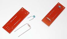
The assembling is done as follows:
- Firstly, the two SMD resistors (R2, R3) are soldered to the conductor path side. Due to the large 1206 type, this is comparatively easy. At first, cover one pad with solder, then hold the resistor to the pad with a pair of tweezers. As soon as the part fits correctly, do the same with the other connector.
- Bend the pins of the through-hole resistor R1 in the correct width. You can use a bending tool. Insert the resistor into the holes. Fixate the resistor with a piece of tape. Turn the PCB around and solder the pins. Cut the remainder of the pins with a sidecutter.
- Repeat with the capacitor (C1).
- If you don't like the white case of the display, paint it black using a permanent marker.
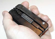
- ICs usually don't come bent to the 2.54mm grid common in through-hole technology. You need to bend them to that grid first by either using a bending tool or by hand (see photo). Additionally, it is recommended to pre-tin the pins of the display a bit with solder.
- Now it's time for a tricky bit: The dot-matrix display and the IC need to be soldered in at the same time. Insert the display from the top and apply a bit of tape to hold it in place, but don't solder it in yet! The display is supposed to fit into the pads with the larger holes. You can recognize the first pad for the IC by it's squre shape (Pin 1). The first pin of the display is labeled with a small "1" or a dot. The pins of the display needs to be cut so that they'll stick out of the PCB by about 1mm. Insert the IC from the opposite side. This requires a bit of trial-and-error until all the pins fit.
- Solder the pins of the display and the IC. Apply a bit of solder flux to achieve better bonding. As we're soldering directly on the pins themselves you should wait a while after soldering one pin so that the parts don't overheat while soldering (this could break the uC)
- Insert the button and the pin header on the top and solder it from the bottom.
- Solder the two wires (red = positive, black = negative) to their corresponding pads. Then cut the wires to the desired length. To reduce mechanical stress you should guide both cables through their cable holes in the top of the PCB.
- Last Step! You need to solder the wires to the battery holder. You need to make sure that the polarity is correct, as the hacklace doesn't provide polarity protection. You may want to bend the pins of the battery holder so that you don't prick your neck.
 |
 |
 |
Flash the firmware
To flash the firmware you'll need an AVR programmer (the USBAsp is such a programmer). Connect your programmer to the ISP interface on the hacklace.
The fuses for the attiny4313 need to be adjusted so that the controller runs at 4 MHz from it's internal RC Oscillator. The fuses are: Low: 0xE2 High: 0xDF Extended: 0xFF
Set the fuse bits using avrdude:
avrdude -v -c <PROGRAMMER> -p t4313 -U lfuse:w:0xe2:m -U hfuse:w:0xdf:m -U efuse:w:0xff:m
Replace <PROGRAMMER> with your used programmer, e.g. usbasp
Now program the firmware and the eeprom configuration data.
Program flash and eeprom using avrdude:
avrdude -c usbasp -p t4313 -u -U eeprom:w:Hacklace_Rev_B.eep
avrdude -c usbasp -p t4313 -u -U flash:w:Hacklace_Kingbright_TA.hex
Software
Compiling the firmware
The firmware for the attiny4313 was developed using AVR-Studio 6.0 from Atmel (AVR Toolchain Version: 3.4.0.663 - GCC 4.6.2). The contained file "iotn4313.h" has an error. A corrected version of that file is available in the GIT-Repository. Place the corrected file under Windows to "C:\Programme\Atmel\Atmel Studio 6.0\extensions\Atmel\AVRGCC\3.4.0.65\AVRToolchain\avr\include\avr".
If you're compiling manually using the avr-gcc toolchain, you should pass the compiler flags "-Os" (to optimize code size only) as well as "-DF_CPU=4000000" (to set the target CPU frequency to 4MHz).
Display Memory
The hacklace uses 200 bytes of display memory. Each byte represents one column of the display. The hacklace uses a proportional font by default. As such, most characters have a width of 4 columns plus one empty column for spacing. Animations are composited of single frames, where each frame requires 5 bytes. The maximum animation size is 40 frames, so also text messages are limited to about 40 characters.
Configuration
You can store custom texts and animations via a serial interface. You'll need a 3.3 or 5V serial cable. Connect it to CON2 (Pin 1: GND, Pin 2: TxD, Pin 3: RxD). Serial configuration: 2400 Baud, 8 data bits, no parity, 1 stop bit [8N1]).
The text file configures your own texts or animations. You can edit it with any text editor. Make sure you're using an 8 bit ASCII encoding; UTF-8 is not supported. The maximum length of the configuration file is 256 bytes due to the microcontroller's eeprom memory.
You need to send a specific init sequence to avoid programming by accident. Send the following sequence to your hacklace:
Escape-Character (ASCII Code 27, resets the hacklace)
Capital H, Capital L
Now you can transfer the configuraion file. It is recommended to reset the hacklace again after you've transferred the file. This enables write protection.
Configuration file format
One messge is either one text or one animation. You can cycle though the messages by pushing the button. Each line of the configuration file contains exactly one message. A message always begins with a mode byte, followed by text or the data of the animation. A mode byte of 0 designates the end of the message list.
The mode byte is defined as follows:
- Bit 7: forward (0) or backward (1) scrolling
- Bit 6..4: Duration of the pause after the end of the message
- Bit 3: Text (0) or Animation (1)
- Bit 2..0: Scroll speed
Don't set all bits to zero, as this designates the end of the message list.
You can enter texts as plain text. You can use any printable 7-bit ASCII characters as well as the german umlauts (Hacklace charset).
The hacklace firmware supports escape chars to make entering special chars, animations and byte values easier:
- Prefix with a '^' to increase the char value by 63. Example: '^A' represents the first special character (129), '^B' the second (130).
- Prefix with a '~' chooses an animation stored in flash. Example: '~A' chooses the first animation, '~B' the second one.
- Prefix with a '$' to enter hexidecimal values. Example: '$10' or '$A1'. You need to enter exactly two values. Only capital letters are allowed. Use space or colon to exit the hex mode.
- Use '^^', '~~' or '$$' to represent the literal value.
You can program own animations by entering the direct mode using '$FF'. Any bytes now entered will be directly stored into flash. Each byte represents a display column, where bit 0 is the first line and bit 6 the last line. bit 7 is not used and should be set to 0. Exit the direct mode by sending a character of value 255.
Configuration example:
$45,Sample text
$40, Very slow scrolling
$47, now very fast
$74,medium speed with pause
$84,.bidirectional.
$44,Umlauts äÄöÖüÜß
$24,A heart ^R
$3B,~F
$0C,$FF $55 $2A $55 $2A $55 $2A $55 $2A $55 $2A $FF,
$00,
Creating animations
You can use the hacklace animator tool to create own animations: https://github.com/Hacklace/Animator/wiki/Download
You need to create your own header file if you wish to replace the animations. That header file contains your animation data as byte array. Include a #include command into "animations.h" which will include your own header file. You'll also need to append your animation to the list of animations (animation[]). The position inside that list defines which character is assigned to it. For example, '~A' is the first animation inside that list (see Configuration File).
You can use the Hacklace Template to make it easier to create animations. It is a greyscale image with 40 frames with 5x8 pixels each. You can simply draw your frames using a bitmap paint program. The last line (8) is not used. To turn on a pixel, draw using color code 0, to turn it off draw using color code 255. Greyscale values are ignored. Crop the image to the number of used frames. Use the script "make_data.m" to convert your image to a C header file. Enter the file name without extension, e.g. make_data('my_animation'). You'll need FreeMat, a free Matlab clone.
Download
| File | Format | License |
|---|---|---|
| Schematic | CC-BY-ND | |
| Bill of Materials | CC0 | |
| PCB etching template | CC-BY-ND | |
| Assembly Plan (front and back) | .pdf, .pdf | CC-BY-ND |
| Firmware (Display Kingbright TA07-11) | .hex | CC-BY-NC-ND |
| Firmware (Display Kingbright TC07-11) | .hex | CC-BY-NC-ND |
| Firmware (Display HDSP-5403) | .hex | CC-BY-NC-ND |
| EEPROM hex file | .eep | CC-BY-NC-ND |
| Source code (Github) | [1] | CC-BY-NC-SA |
All files are published under the respective Creative-Commons license.
Pictures
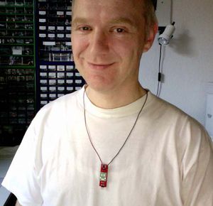 |
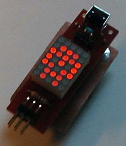 |
The belt clip was made by attaching the battery holder to a PCB and connected using soldering lugs.
You can see the hacklace on a video on YouTube [2].
Ordering Information
In Germany, you can order all needed parts from Reichelt or CSD-Electronics. A list of parts can be found here.
Kit
You can purchase a kit for 10€ at RaumZeitLabor - please contact muzy.
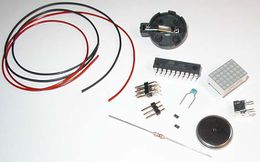 |
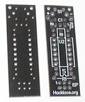 |
 |
Credits
Hacklace was inspired by the "TinyMatrix" project from TigerUp [3].